- Introductory components
- Installing the CPU & memory
- Casing & installing the motherboard (aka mobo)
- Graphics, soundcard & add-on cards
- Internal & external media drives installation
- Cabling, PSU, case LED lights & power button
- Additional cabling for output ports
- Finishing touches, power on self test (POST) & BIOS
- Operating system installation (Win XP)
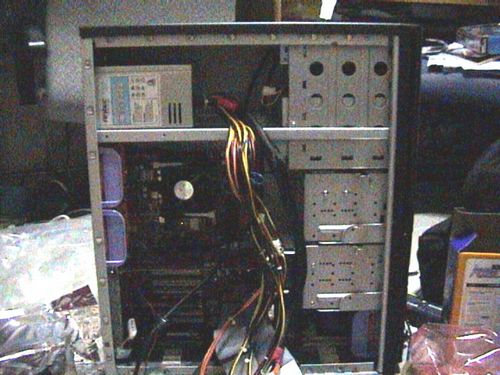
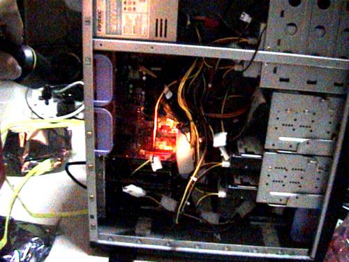
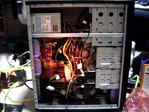
Cabling, PSU, case LED lights and power button
With all your major components now assembled, it’s time to link them up with the power supply unit which essentially, feeds power to your your connected components when the system is turned on.
PSU installation
The PSU (power supply unit) provides electrical power to all the components you have on your computer (Eg All drives, motherboard, etc) and send output voltages based on fixed rail voltages – e.g 12volts, 5volts etc. Upon releasing the wired beast from the packaging, locate the ATX 12V power supply plug (20 pin rectangular connector, usually the largest).
This will go into the motherboard ATX power connector plug to power the motherboard and its components, some PSU have an adapter for an additional 4 pins which you can clip along side the 20 pins for motherboards which require 24 pin power connectors, though this is found mostly on newer boards which require a larger power input. Another smaller square 4 pin ATX connector provides power for the CPU (JPW1), the rest of the cables will go into your other components such as drives.
Type of power connectors
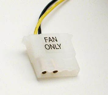
You will notice that there is quite a few smaller rectangular flat molex 5V power (4pins) connectors, which look as similarly pictured, these are 12 volt supply and will go into your CD-ROM drives and hard drives. Coincidentally, your casing fans will also feature the same molex 4 pin connectors, usually these are labeled “Fan only” and feature 5volt output, these will plug into your casing fans.
Do also note that some fans can take the regular 12 volt output as well, particularly those with additional funky LEDS or temperature readouts and/or with variable RPM with a temperature sensor, these may not even power up on a 5 volt line. If you have many fans, you might want to consider getting a power Y-cable splitter to run more fans in parallel.
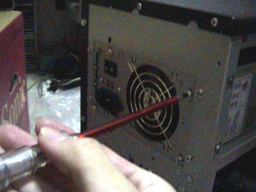
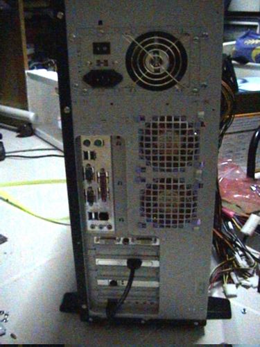
As with most casing, the PSU will normally go at the top back of the casing, secure the unit into the casing using the provided screws and secure it tightly. PSUs can be one of the nosiest units in the whole computer. Insecure PSU rattling in resonance with the spinning fans due to improper fitting of the unit, what’s more the screws connecting the PSU and the case serves as a ground linkage for safety as well so your PC case will never have the risk of being “live”.
IDE Cabling
I believe I touched briefly on hard disk cabling a section before, so this is the part where you physically get to connect them.
SATA or IDE cables are most probably included bundled in your motherboard package, otherwise head down to any computer hardware store and get them. You need one SATA cable for each drive, while an PATA IDE cable can take 2 hard drives in master and slave configuration. The same is for one IDE cable for two CD-ROM/internal Zip drives as well. Lastly, the floppy cable is dedicated for one floppy drive.
Many PC part stores sell cables in different lengths and makes, let be thickness, so if you are using a mid or full tower casing, its good to get longer-than-standard cables for reach. For smaller casings, standard (or shorter) cable lengths are recommended to prevent unnecessary clutter with the casing. Though you can always tie up excess cable with a cable tie for neatness.
ATA cables are used for hardrives for maximum transfer speeds (ATA-100 for 100MBS and ATA-133 for 133MBS), while SATA I & II goes at ATA-150 and beyond, depending on your motherboard generation. SATA is backwards compatible so SATA 3.0 can work with SATA I in generally. The same rule still applies- one SATA cable per motherboard connector per drive device, so there’s no jumpers or configuration to worry about.
For PATA IDE cable, some cables have a third output in the middle of the cable, that output is used only if you are intending to connect a slave drive in that particular IDE port. One end of the ATA cable will connect to the motherboard, on the other extreme end, into your primary master drive (make sure you’ve set the jumper settings corrected to MASTER, head to the previous drives installation section on setting jumpers if you’ve not caught that part).
Floppy cable install
The floppy drive had evolved much over the 5.25″ floppy disks to the 3.25″ variant we see today, these days, floppies are dying out and you usually do not need them considering that PCs these days can boot from thumb drives or external mass storage devices- areas where floppies used to proved invaluable in the past.
Having said that, installing a floppy drive is purely optional now, infact many PC manufacturers do now feature such a drive unless you request for one.
Installing a floppy drive can be a easy one step affair or a nightmare depending on your setup. Unmistakably, the floppy drive has always been the most notorious and troublesome drives to install in computers. Firstly because many manufactures do not follow the same standard settings pin setting and some even manufacturers have them reversed. Installing it is very much of a trail and error game, trying to find the correct slot configuration.
To detect whether you have this problem (widely named as the curse of the floppy drive syndrome), upon turning up your computer later, you will notice that your floppy drive light will always stay on during operation and won’t go off. Try not to insert any floppy disks into the drive when that happens, as it have the capabilities of destroying any floppy disks it consumes.
To fix this “always on problem” when connecting the floppy cable, you must completely stick the the 1st pin to red connector rule. Even if the floppy cable have notches on them, allowing them to be inserted to the drive in one direction, you have to still find a way to get the floppy cable’s 1st red cable (identified as the 1st red wire strip on the cable itself) to be in line with the labeled 1st pin on the floppy drive itself.
My Sony floppy drive have the pins reversed from that of the floppy cable provided by my motherboard manufacturer. Given this problem, you can get another floppy cable with the notch revered, or you can do what I’ve done- I filed the notch on the connector end of of the cable so that it can be inserted into drive in the opposite direction. And wollia it works in the end.
LED lights and power button
Ok, now, onto connecting the LED lights, power and reset buttons of your casing. Firstly, locate the front panel cables in your casing and identify them. Usually it will be a long string of thin coiled wire running internally from the front of your case. These cables are usually attached to a simple push button switch which in turn is simply held in place using glue, so it’s very fragile and you should not tug on this cable. This cable will connect straight to your motherboard power and LED activity pins.
Secondly, from your motherboard manual locate the front panel pin connectors (usually labeled JFP1 & JFP2) JFP2 is a so-called standard specification with only the power button and computer mono speaker functions. While the JFP2 pins, which are of intel specifications, have power and hard drive operation LEDS outputs, reset and power buttons outputs. Plug the respective cables to their motherboard pins.
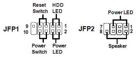
Following each pin plug, plug each of them into the labeled pins on your motherboard. Some cases have the pins all fitted in a plug which can be fitted only one way and can be inserted with ease, while others might have them separated, so you might want to tape them up with duct tape to make it into a big socket where you can simply just plug into your motherboard.
Generally there are 5 components you need to wire up, you can use the diagram above as an illustration of how the layout could be:
- Power button – usually 2-3 pins
- Reset button – 2-3 pins
- ON LED – 2 pins
- Hard drive activity pin – 2 pins
- Case speaker (for troubleshooting) – 2 pins
Usually each JFP1 is not isolated to the other, you need to use both of them for a comibination of features can one can work without the other. You can have both the power and HD LEDS, power and reset buttons from the first set and the speaker from the other connector. Do note that the arrangement of the pins differs from motherboard manufacturers, but this shouldn’t be much of a problem.
Well, that’s all about the basic cabling, now to cover on additional miscellaneous cabling you might encounter.
- Introductory components
- Installing the CPU & memory
- Casing & installing the motherboard (aka mobo)
- Graphics, soundcard & add-on cards
- Internal & external media drives installation
- Cabling, PSU, case LED lights & power button
- Additional cabling for output ports
- Finishing touches, power on self test (POST) & BIOS
- Operating system installation (Win XP)
")