
Jus came back from the *test* early this morning. It some DSO labs assessment thingy @ science park- to determine whether you will be sweating out in the fields or sitting in front of a computer and working for the laboratories during National Service. It kinda whocked up when they say that you are the *specially selected* few for the vocation and *duh* its only 50-60 people in the whole of SG??? “Me veri normal don’t find me very special Leh!” Ok, back on topic, Its similar to the commando selection I’ve last year, but all paper work only. & man the test was all greek to me, mostly networking, solaris and unix questions, I only scored in the hardware and web site parts. The questions, when its difficult, it real tough, when it easy it really damn easy *duh* finished record time in half the the aloted time, cos the first to finish is the first the Go!
Site up & functional

The site’s pretty well much up and running already. Dude, did the tons of php coding on the blog entry and comments section- sure kinda whocked me up in the afternoon, till I got it fixed after dinner. Added cookies functions so you don’t need to retype your nick and stuffs each time you post any comments, keke, so much for THE SITE… Moreover…and.. damn, will be waking up early for the first time in 2months for some NS vocational assignement thingy at science park tomorrow morning, hope I can fall alseep by 12 tonight, cos normally 2am is my usual bedtime *duh* gotta stop drinking coffee already.
Design Version 10 up!
Ok, as promised, V10.0 is up dudes! feel free to romp around the site.
In the meantime, I have to adjust some pages to fit the new color scheme, so please bear with it. Also, a comments section is up, but its still very very buggy.
Me? Linksys winner?
Lolz, won in some little Linksys lucky draw, me puzzles of how I entered.. then, yea must be danged router I’ve brought from them last year… hehheh.. got the 10th prize linksys gift pack.. *duh* check out this link, and yea my name’s there too. When you come to think about it, in the whole of Singapore, mmm, out how many people who brought linksys products, about 80 ppl won…MMmmm..
dang! mind my babbling! cos I am thinking bout the math involved and the probalblity of winning.. *DUH again* sips coffee to get me going.. well, its just lucky me…
Ok, on the site. I have the lastest design finalised tomorrow, noon (the time which I normally wake up in mornings) the colour scheme you see here (yellow, black) is a small preview to what you can expect tomorrow. In the mean time, take time to appreciate ver 9.0, cos v10.0 is here to RULE.
Woo news page up!
This is a news test page. The news section will be up on friday afternoon (8+ GMT). Sorry for any inconvience caused
Functional check 2
Got the new blog system up, ported from my previous databases, so here goes, test test testing, 1, 2, 3.
Build your own personal computer- Finishing touches and POST

- Introductory components
- Installing the CPU & memory
- Casing & installing the motherboard (aka mobo)
- Graphics, soundcard & add-on cards
- Internal & external media drives installation
- Cabling, PSU, case LED lights & power button
- Additional cabling for output ports
- Finishing touches, power on self test (POST) & BIOS
- Operating system installation (Win XP)
Finishing touches, power on self test (POST) and BIOS
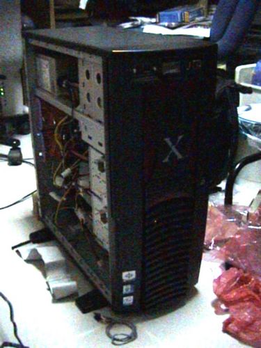
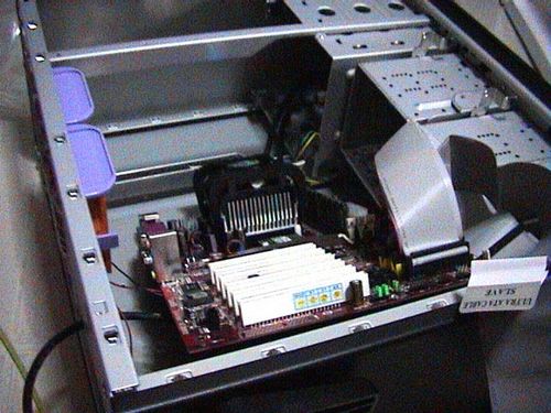
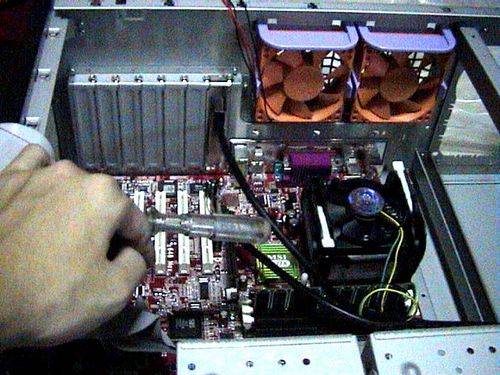
Now to do alittle house keeping before closing up your PC enclosure. Here I will talk about good internal wire placement and layout. It is generally good to keep power cables arranged neat and in order so as it does not obstruct heat dissipation, air flow and operation of moving parts (e.g. fans). As you can see, after assembling the PC, the case is very much like a big Medusa mess of wires.
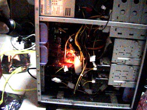
Though your system can run in this mess and may seem insignificant now, it goes a long way in promoting smoother, cooler internal operation resulting in fewer lockups, lesser equipment failure and longer equipment life. Improper ties cables can get caught in your fan blades, cause necessary noise or vibrations of even create pockets of air spots which built up internal case temperatures over prolonged use.

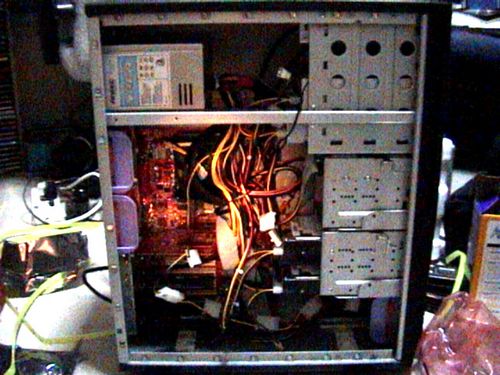
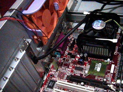
You can always tidy up the case using cable ties, the general rule is to make all areas where air flow is evident, that is the suction and exhaust areas near the fans. Air generally gets sucked in from the front of the case and blow out at the back, the air flows over your processor and graphic card, which are major heat generators as well as your hard disk, so you do not want any obstacles in the way of this air flow.
Once done, the following are all cosmetic clean ups, like exterior touch ups are kinda fun thing to do too, first with the pasting of the “all important” intel and motherboard stickers.
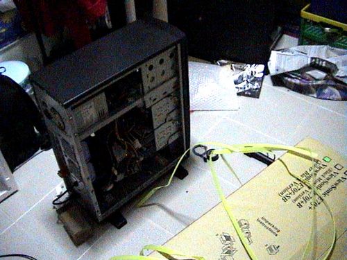
Building your PC can create quite a mess where you are, if tidiness is your cup of tea, you might want to tidy up the area before booting up. Ok with that lets get on with booting up this system.
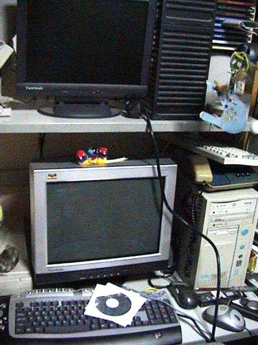
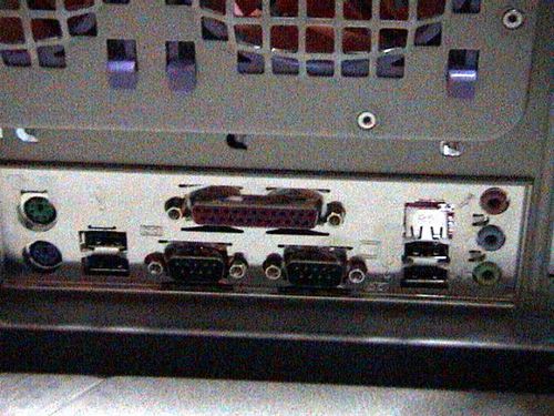
Now is the magic moment we had been waiting for, making sure your system actually works. Start by plugging in all your required input and output devices, such as monitors, keyboards and mice, ensure they are all powered on and standby. If you have audio, plug in your 3.5mm audio cable and power on your speakers, the same for network with wireless or ethernet cables.

POST
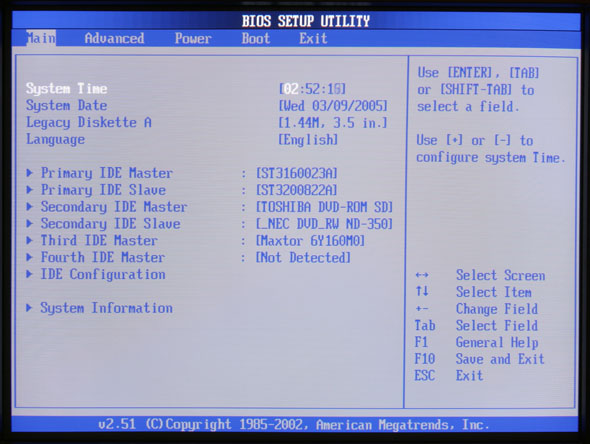
The post (power on self test) is the first thing you see when you first boot up your computer, and that the time when the computer checks for all the connected components, (processor, amount of ram, connected drives.. etc). If you can see the start-up screen and you enter the bio setup, its an indication that everything’s all set right and you can go onto installing your operation system. If everything is ok, the system will just go through all the component checks and eventually stop after the IRQ check or so. The system will continue in this loop until you specify a boot device, which is configurable in the BIOS which I would touch on soon.
What to do if you see nothing on screen
If you do not see anything on-screen after turning the unit on, look for symptoms: Are the fans spining? any harddrive activity? or is your video card not properly inserted? such small tell tale signs can lead you to the problem. Turn off the computer, unplug the main power cable and check that all connections (video, power connectors, add-on cards) are secured and properly plugged in. Do a thorough check on all components and be sure on that. When you are done, close everything backup, plug in power and retry.
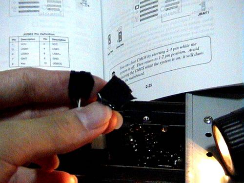
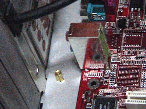
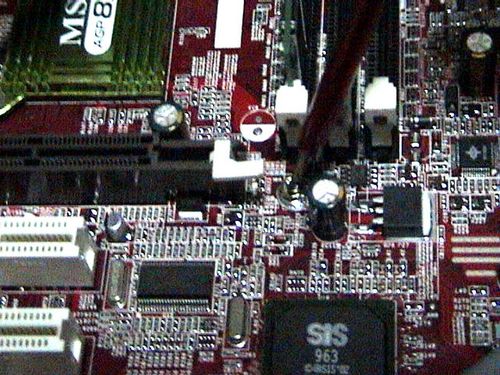
If you’ve got everything checked, it is sometimes ideal to reset/clear your CMOS and restart the POST procedure again, it can be done by shorting the CMOS (JBAT1) connector jumpers on your motherboard. (do so when your computer is off and mains power off, or you can get permanent board damage).
As always, consult your motherboard manual if you are in doubt where the clear CMOS jumpers are.
The BIOS
In the BIOS (basic input and output system), you can check the number and type of hard disk, CD-ROM drives you’ve connected, so are the processor info, type and amount of ram you have, this is useful for checking on connections. Included too, are certain diagnostics tools if your board have that feature. You too, can enable of disable certain additional properties such as SMART for hard disks, quick boot feature etc, enable/disable plug and play, on board integrated sound if you intend to use a separate sound card for audio output.
One important thing to do here is to change the boot sequence of your computer if you intend to install an operating system later. If you are using Windows 7, Vista or XP, Linux, FreeBSD, etc, set the first boot device to CD-ROM, for windows 98 and thereafter or alternative, you need a boot up floppy for installation, so select floppy drive as the primary boot drive. Some newer motherboards will auto detect and select a boot device based on what is detected let be installing from a mass storage device or a thumb drive as well, so sometimes it can be done automatically, though you might want to set the option manually and not leave it to chance.
Just explore around, who knows the your BIOS may have some unexpected new features, use the manual as a guide if you do not understand certain technical terms, its always there.
Advanced BIOS tweaking and overclocking
You can fine tune your system by changing certain processor core voltage, graphic card voltage, memory latency for improved performance. If you do not intend to do an overclocking or so, just leave everything as the preset default or normal settings as this is not recommended in the preliminary rounds of setting up your new system. But you can do so after you’ve got the system set up and stable.
With your system up and running, it is now ready to accept the operating system install to get it up into a system which you can actually use.
- Introductory components
- Installing the CPU & memory
- Casing & installing the motherboard (aka mobo)
- Graphics, soundcard & add-on cards
- Internal & external media drives installation
- Cabling, PSU, case LED lights & power button
- Additional cabling for output ports
- Finishing touches, power on self test (POST) & BIOS
- Operating system installation (Win XP)
Build your own personal computer- Additional cabling for output ports

Article table of contents
- Introductory components
- Installing the CPU & memory
- Casing & installing the motherboard (aka mobo)
- Graphics, soundcard & add-on cards
- Internal & external media drives installation
- Cabling, PSU, case LED lights & power button
- Additional cabling for output ports
- Finishing touches, power on self test (POST) & BIOS
- Operating system installation (Win XP)
Additional cabling for output ports
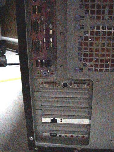
So what’s all about the front panel output ports? These section focuses on connecting the connectors found at the front of your casing, these can be audio cables, USB, firewire ports to important items such as your power and reset button.
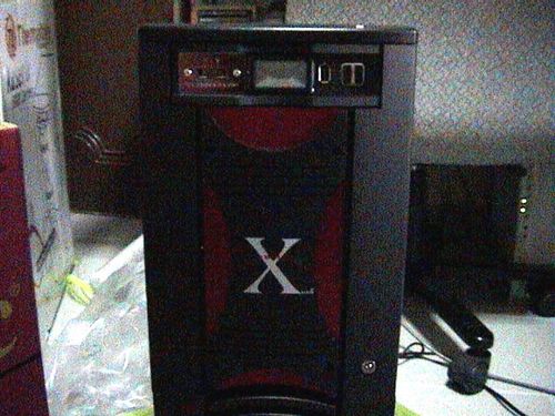
Nowadays, output ports are readily available as an good option for many DIY people out there. It allows external devices to be plugged in directly in front of your computer’s casing. The type of output ports can range from the all common USB to firewire, audio, parallel, game and serial ports. In fact, it’s safe to say that for any ports you find at the back, you are sure to find a similar panel option at the front. Some of them come integrated into the case itself, while some come in the form of add-on parts, such as the Thermaltake hardcano 7 in one such example spotting firewire and USB as shown below on the top of the casing.
Most motherboard manufacturers these days include expansion ports on top of those offered as standard at the back output of the motherboard. They usually come bare with pins on the board itself and require accessories such as an S-bracket or and external connector to route the input externally into a proper USB port, usually through specially fitting plugs which fits the pins. We usually see 2-4 additional USB port from these expansion pins, but the total number of ports too varies from motherboard to motherboard.
The motherboard I am using as an illustration here have 4 USB 2.0 ports at the back of the motherboard and 2 USB 2.0 expansion ports. Each USB port typically requires the following connection to work and they are identified as individual pins for each USB port (usually labeled USB0 and USB1, etc).
1st USB Port
- VCC
- USB0- (USB – Negative pin)
- USB0+ (USB – Positive pin)
- GND (ground)
- KEY (Optional)
Consult your motherboard manual on its availability and also, to locate the pins to where the the extra USB ports can be connected. It should contain info like where the VCC, USB0-, USB+, Ground and key pins are located. Each (One) USB port requires you to connect to all the following 5 pins in total for each port. While some connectors come with a separate lead for each pin, some motherboards feature and assembled plug which you can simply just plug in one way without having to go through the connectors pin by pin.
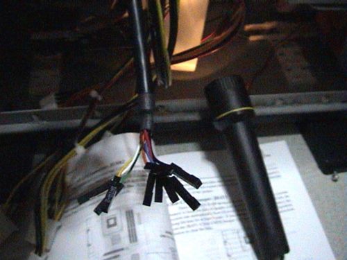
As shown on the left picture below, the connectors I’ve got from my Hardcano 7 USB output ports come in messy connector combination and not like those multi-pin pin connectors, where one plug is all you need to get one port working. Given this messy but flexible combination (as not all motherboard manufacturers have the same pin allotment, separate pins connectors are recommended to fit all different type of boards), you have to start on the painstaking task in plugging the connectors to the respective motherboard pins one by one.
Lucky for me, I decided to arrange the connectors in order as the pins shown on my motherboard. Then a simple dash of electrical tape to secure them altogether (on upper right fig) to keep them in order before plugging it with one easy short on the mobo. Do it so for all the ports you have and as simple as it is, it all pretty easy!
Other types of cabling
In addition to that, some output port panels do not necessary require you to mess with pins, but rather uses one of the your rear USB ports and extends the output to the front of your case into a hub. The same can be said if you wish to send an audio input (e.g like your microphone) or and output to the front, the most widely used way is to use a cable extender.
These extenders go from the front, through your whole casing and come out at the back slots and looping back to connect to your motherboard back output ports. This is useful if your board do not have the additional expansion pin port option and want to allow easy front connection of your back plate be extended to the front through of your enclosure’s front output port panel.
With these cabling done, we shall touch on the finishing touches for your system.
Article table of contents
- Introductory components
- Installing the CPU & memory
- Casing & installing the motherboard (aka mobo)
- Graphics, soundcard & add-on cards
- Internal & external media drives installation
- Cabling, PSU, case LED lights & power button
- Additional cabling for output ports
- Finishing touches, power on self test (POST) & BIOS
- Operating system installation (Win XP)
Build your own personal computer- Internal and drive installation

- Introductory components
- Installing the CPU & memory
- Casing & installing the motherboard (aka mobo)
- Graphics, soundcard & add-on cards
- Internal & external media drives installation
- Cabling, PSU, case LED lights & power button
- Additional cabling for output ports
- Finishing touches, power on self test (POST) & BIOS
- Operating system installation (Win XP)
Internal and external media drives installation
This part now talks about the installation of your internal & external media drives, this includes your CD/DVD-Rom drive as well as your hard disk drives.
Preparing to install
First off, for most cases, it is always common to have the larger 5.25″ bays (for mostly cd-media drives) ontop of the 3.5″ bays (for floppy and hard disk drives), this is better as most ATA cables (which connects to your harddisk) are generally shorter than that of other IDE cables which connects to your external media drives, though longer ones can be always purhased at any local hardware store.
Also, generally, the way you install the drives on your computer depends greatly on the design and features it have (eg, availability of rack rails, drives cages, etc) and it differs from one type of casings to the other. Brands like Cheiftec, Lian-Li, Antec and Thermaltake are better case makers out there and have better installation features.
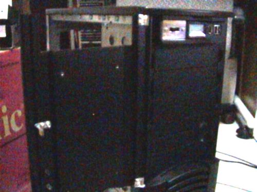
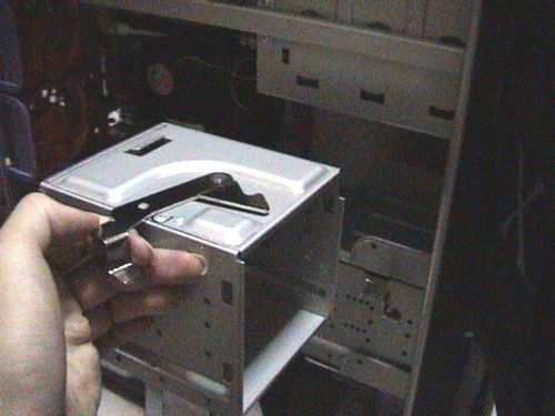
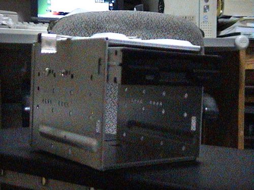
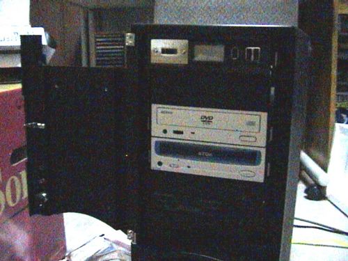
On the casing I am using(Fig 5.1), we can see that all bays all are covered by a a sealing plastic cover. To remove these covers, just release the locking hatches behind them through the interior of the casing. Some case manufactures like thermaltake also have pre-casted steel protection plates behind the covers (Fig 5.2), and can be easily removed with some simple twisting motion (similar to that of removing pieces from plastic model kits)
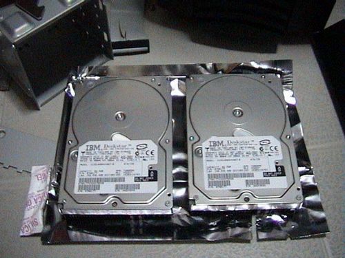
With all that done, lets prepare the drives themselves. Harddisk these days come with 2 types of connectors for mainstream computers- SATA and PATA, generally SATA is an improvement of parallel ATA or P-ATA for short, it rated at ATA-100/133 while SATA can go up to ATA-150. Nafive to PATA drives is the need of the trademark IDE ribbon cable which in turn requires jumpers to be set properly on the integrated drive electronics (SATA harddisks do not have jumpers).
Drive jumpers
Ok, onto the jumpers, jumper configuration differs from drive to drive, and luckily, almost all manufacturers have the jumper settings printed onto the drives themselves. These are usually located at the back of the drive where the connector pins are, look for a sticker stating the position and orientation fo the jumpers to set the respective MASTER or SLAVE option, it;s fairly straightforward. Usually upon purchasing a drive, it is usually set to the MASTER setting by default.
If you intend to install a second drive using that same motherboard slot, the 2nd drive must be set to the SLAVE jumper setting in order to function. You have to remove the jumper and rearrange it in accordance of the set up diagram provided by your manufacturer. To remove jumpers use a screwdriver (or alternative sharp object), gently lift the jumper out of the pin slot and later, place it back in the defined SLAVE setting.
Internal hard drives
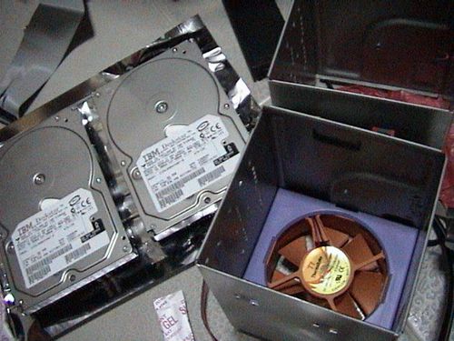
I am intending to use two hard drives for this system. As stated, this casing have removable hard drive cages, which makes installation easier by mounting drives out of the system and locking the cage back in when done, thus no need to cramp within the confined boundaries of the interior and securing in the hard disk to metal frames internally. Some cases have a better evolved system where you can simply just slide the drive into bays already made for hard disks and simply just click them into place without tools, so it varies between manufacturers. If your system have no cage feature, don’t fret, just follow on the review on installation, only that you have to do it within the fixed bays in your casing.
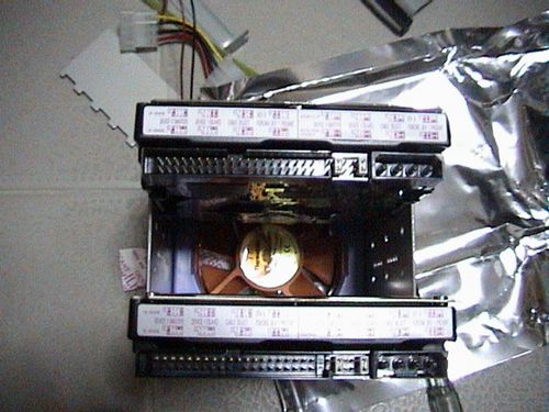
As we can see below, thermal take has included a single cooling fan in one of the harddrive cages (Fig 5.3) which can accommodate 3 hard disks. These drives can run pretty how after sometime, so the general tip here is to install the drives in a manner which allows the maximum airflow on either side of the drive. If you are installing one hard disk, it would be ideal to install it in the center of the cage, where air blowing from the fan can flow both above and below it, thus providing better and more effective cooling. For 2 drives, one would go on the top while the other, at the extreme bottom of the 3 available mounting places, (Fig 5.4) where airflow is still possible between them.
I have no intentions to do a water-cooled system on this computer so fans would do great at the moment, anyway I find water-cooling your harddisk enclosures bit of an overkill as you can’t actually “overclock” these babies, and why should you?
External CD-media drives
Removing the 2nd 3.5″ harddrive cage (fig 5.5), this is where you can install additional hard disk or any 3.5″ external drives such as a floppy drive or a multi-card reader, in this case, it would be used to hold my floppy disk drive.
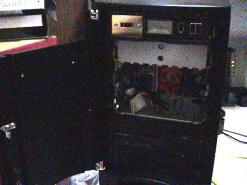
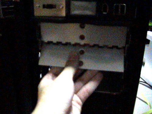
Now to install the DVD and CD drives, we focus our attention to the 5.25″ drive bays above. With front the metal plates removed on fig 5.6, time to install them.
The 5.25″ drive bays are little different from the 3.5″ cage, the casing employs Chieftec rails to rack mount the bay drives, which are stored within the casing itself to prevent misplacement. Before happily screwing in the rails, you have to locate the right depth alignment of your rails and your drive, or your drives will either stick too far out, or too shallow of the casing. You need a little trail and error for this.
While holding the rails beside the drive, test-slot the drive into your casing to locate the rail holes where the screws go in nicely on to your drive, remove it and secure the rails onto the drive with respect to those holes themselves. Do so for all drives you intend to install and just slot them into any 5.25″ bay slot you seem fit.
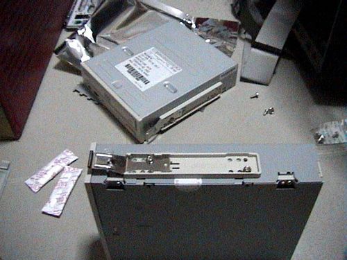
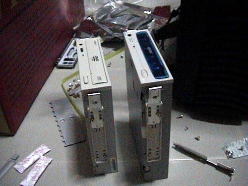
After you are done, the drives can be removed without tools by simply unlocking the rail clips and sliding the drive out. Perfect for quick drive swaps. With all drives done now to it’s time to wire them all out.
- Introductory components
- Installing the CPU & memory
- Casing & installing the motherboard (aka mobo)
- Graphics, soundcard & add-on cards
- Internal & external media drives installation
- Cabling, PSU, case LED lights & power button
- Additional cabling for output ports
- Finishing touches, power on self test (POST) & BIOS
- Operating system installation (Win XP)
Build your own personal computer- Graphic and add on cards

- Introductory components
- Installing the CPU & memory
- Casing & installing the motherboard (aka mobo)
- Graphics, soundcard & add-on cards
- Internal & external media drives installation
- Cabling, PSU, case LED lights & power button
- Additional cabling for output ports
- Finishing touches, power on self test (POST) & BIOS
- Operating system installation (Win XP)
Graphics, Soundcard and addon cards
Installing cards are considered one of the most easiest things to do on DIY, it is just mostly locate, align, slot, align and secure. For most cases, you will require just a basic screwdriver to secure the cards in place on the rear mounting slots of your case itself. If you enclosure feature plastic tool-less clips for card installation, the better. Just follow this few ‘golden rules’ and you will be fine for all kind of cards in general.
Graphic card install
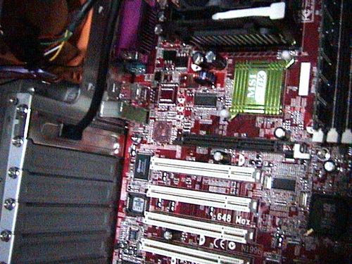
Modern day motherboards should have at least a graphics port slot it can come in PCI-E or AGP formats for older boards. It can be identified as the slot closest to the processor or north bridge or the only port with a locking mechanism. It is also usually the shortest port and is normally located on the top of the line of PCI slots. Other performance boards can feature dual PCI-E slots either in PCI-E 1.0 or 2.0 to allow SLI or crossfire configurations. For 2 and up to 4 GPUs to be linked together.
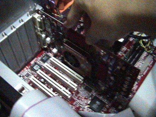
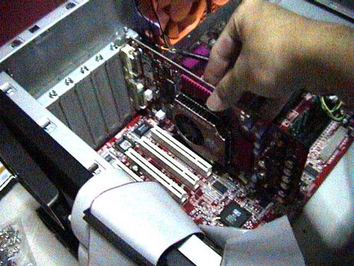
Optimal card placement
What I am focusing here is nothing much on how to find the best way to install an add-on card or the nicest way of slotting it in, but locating strategic locations for your card. You do not have a choice in the location of the graphic card slot, you however, have a choice on the location for the PCI add-on cards and if you have any, you might want to place them as far as possible from each other.
Having said that, the best location for any add-on card with proximity to your graphics card is at least one or 2 PCI slots away from it. As a video card is essentially a mini PC with it’s own processor itself, it dissipates a lot of heat in operation and breathing space is necessary. This is further more paramount if you intend to do some overclocking. Moreover, extensive amounts of heat from a nearby adjacent card can cause an unnatural build up of operating ambient temperature, which is not efficient technically and might do significant damage of even shorten the lifespan of the cards placed close together. So place great caution on the location of your cards.
Miscellaneous add-on card
Add-on cards will encompass any additional cards plugged in either on the motherboard PCI or mini PCI-E slots, usually for added functionality for the system. For example e.g. Wireless network card, FM/Digital TV Tuner, firewire PCI card and sound cards are few of them.

For my sound card in this case- a Creative sound blaster Audigy card (Fig 4.1), good place to install it in the case is at the bottom row of the PCI slots, leaving a more than enough 5 PCI slots between them for optimum heat flow and better performance. Anymore additional cards will go in between this space. If you have a network card or say a TV tuner, it’s relatively safe to place these cards side by side slotted next to each other as they do not release much heat when in operation.
With the add-one card installed, lets head onto the media drives installation next.
- Introductory components
- Installing the CPU & memory
- Casing & installing the motherboard (aka mobo)
- Graphics, soundcard & add-on cards
- Internal & external media drives installation
- Cabling, PSU, case LED lights & power button
- Additional cabling for output ports
- Finishing touches, power on self test (POST) & BIOS
- Operating system installation (Win XP)
Build your own personal computer- Casing and motherboard

- Introductory components
- Installing the CPU & memory
- Casing & installing the motherboard (aka mobo)
- Graphics, soundcard & add-on cards
- Internal & external media drives installation
- Cabling, PSU, case LED lights & power button
- Additional cabling for output ports
- Finishing touches, power on self test (POST) & BIOS
- Operating system installation (Win XP)
Casing and installing the motherboard
With the processor mounted on the board, it’s time to mount the motherboard into the case itself. This have to be done before the introduction of the various components I will be using thereafter. So lets get on the next step of actually building the PC. Once in, all the various components can follow and be connected to it.
First off, the casing
The casing is one of the most important unit of the whole PC, as of course it houses all the necessary components for operation. Well, unless if you want to run your bare PC case less, that’s an exception- This is one thing you shouldn’t miss. Going into more detail on the casing now, this Thermal take casing I’ve got is a mid-tower server casing which can take ATX sized boards or larger. M-ATX are compatible too as well given the standards for dimensional mounting holes across all sizes of motherboard.
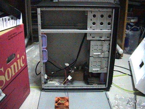
It have four 5.25″ external bays, two 3.5″ and four 3.5″ internal bays (removable bay cages).
This is an air cooled case, so fans will be the talk of the town here. Fan wise, Thermal take has really decided to put all they’ve got into their first line of casing, firstly with their fans. At the front we have one single fan mounted in one of the hard drive removable cages. There is also one as a standard system fan at the bottom front. At the side, we have one side blowhole intake fan mainly used to blow fresh air into the processor and graphic card area.
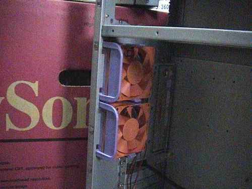
The exhaust fans
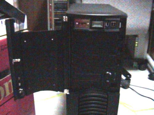
Front SOHO style doors
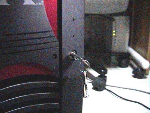
Lock and key
At the back, there are two exhaust fans primary used to expel heat from the processor and board components.
Ok, now to the front exterior- and say!.. they’ve even included a lock and sets of keys for the front and side door. This door is heavy- made completely of bolted solid steel with several metallic pieces mounted and screwed together, giving it that very solid sleek finish. It’s just a pity that for a door this solid, it’s let down by a dingy plastic latch which is the swiveling attachment for the key lock.
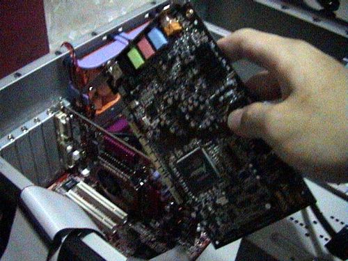
Getting the Motherboard in
First off, one the the main things we have to check before happily screwing the alignment of the board is the back output panel. Obviously, most case-manufacturers do not know what kind of boards you are using and always include a standard output panel which don’t always seem to fit your configuration. That is when the mobo manufacturer come to the rescue- by including in the package, their own cut out panel.
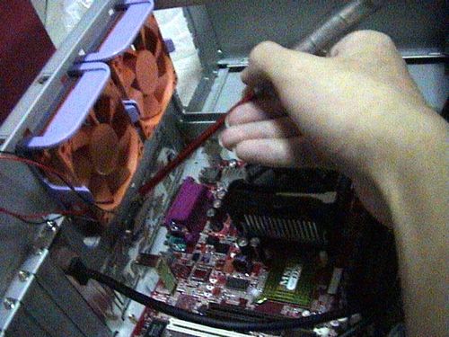
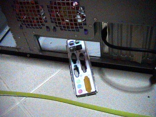
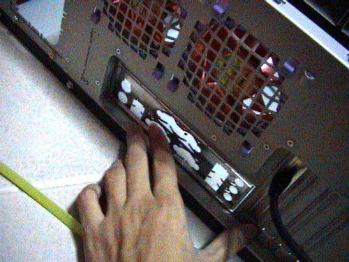
To remove the original back panel, gently use a screwdriver to poke the small securing popped out dots around the edges of the aluminum panel, do so for about majority of them on each side and the a final jerk will force it out nicely unharmed. These back panels are usually tacked evenly around it’s circumference, so just knocking them out will be good enough. One you’ve got that generic panel out, clip in your own glove fitting back panel as provided by your motherboard manufacturer.
Once you’ve got that settled, check the internal side surface of the casing for motherboard spacers (These are the golden stubs we see in Fig 3.2). Spacers are screws which screws in one end and have openings at the top that allows other screws to be mounted onto them. Such spacers are used to actually, space the board from the being in contact with the casing surface. If the casing manufacturer hasn’t pre-screwed them in for you, pop in the motherboard & locate the alignment of mounting holes from your motherboard with the drilled holes on your casing panel and screw them in appropriately.
After getting the spacers in, slowly lower the motherboard on them (Fig 3.3) and get the output motherboard ports to stick out of the back panel. (Fig 3.4) Everything should go well and fit like a glove as most casing and motherboard makers adhere to the same standard ATX dimensions on screwing holes, alignments etc.
Finally, start on the repetitious task of securing all the screws securely into the spacers themselves. It took me quite some time getting all the nuts in, but maybe I think it was just me as its not easy holding the board with one hand and screwing it in freely with the other! When the board and processor finally in and secured. Give yourself a pat on the back you’ve cleared one major huddle. it’s time to add the add-on cards next.
- Introductory components
- Installing the CPU & memory
- Casing & installing the motherboard (aka mobo)
- Graphics, soundcard & add-on cards
- Internal & external media drives installation
- Cabling, PSU, case LED lights & power button
- Additional cabling for output ports
- Finishing touches, power on self test (POST) & BIOS
- Operating system installation (Win XP)