30.6 C
Singapore
Tuesday, May 6, 2025
Home Blog Page 193

Build your own personal computer- Casing and motherboard

0
Tutorial: DIY steps to build your own personal computer

Casing and installing the motherboard

With the processor mounted on the board, it’s time to mount the motherboard into the case itself. This have to be done before the introduction of the various components I will be using thereafter. So lets get on the next step of actually building the PC. Once in, all the various components can follow and be connected to it.

First off, the casing

The casing is one of the most important unit of the whole PC, as of course it houses all the necessary components for operation. Well, unless if you want to run your bare PC case less, that’s an exception- This is one thing you shouldn’t miss. Going into more detail on the casing now, this Thermal take casing I’ve got is a mid-tower server casing which can take ATX sized boards or larger. M-ATX are compatible too as well given the standards for dimensional mounting holes across all sizes of motherboard.

It have four 5.25″ external bays, two 3.5″ and four 3.5″ internal bays (removable bay cages).

This is an air cooled case, so fans will be the talk of the town here. Fan wise, Thermal take has really decided to put all they’ve got into their first line of casing, firstly with their fans. At the front we have one single fan mounted in one of the hard drive removable cages. There is also one as a standard system fan at the bottom front. At the side, we have one side blowhole intake fan mainly used to blow fresh air into the processor and graphic card area.


The exhaust fans

Front SOHO style doors

Lock and key

At the back, there are two exhaust fans primary used to expel heat from the processor and board components.

Ok, now to the front exterior- and say!.. they’ve even included a lock and sets of keys for the front and side door. This door is heavy- made completely of bolted solid steel with several metallic pieces mounted and screwed together, giving it that very solid sleek finish. It’s just a pity that for a door this solid, it’s let down by a dingy plastic latch which is the swiveling attachment for the key lock.

Getting the Motherboard in

First off, one the the main things we have to check before happily screwing the alignment of the board is the back output panel. Obviously, most case-manufacturers do not know what kind of boards you are using and always include a standard output panel which don’t always seem to fit your configuration. That is when the mobo manufacturer come to the rescue- by including in the package, their own cut out panel.

Use a screwdriver to pry the generic plate out
Out at last!
Install your own motherboard panel

To remove the original back panel, gently use a screwdriver to poke the small securing popped out dots around the edges of the aluminum panel, do so for about majority of them on each side and the a final jerk will force it out nicely unharmed. These back panels are usually tacked evenly around it’s circumference, so just knocking them out will be good enough. One you’ve got that generic panel out, clip in your own glove fitting back panel as provided by your motherboard manufacturer.

Fig 3.1
Fig 3.2

Once you’ve got that settled, check the internal side surface of the casing for motherboard spacers (These are the golden stubs we see in Fig 3.2). Spacers are screws which screws in one end and have openings at the top that allows other screws to be mounted onto them. Such spacers are used to actually, space the board from the being in contact with the casing surface. If the casing manufacturer hasn’t pre-screwed them in for you, pop in the motherboard & locate the alignment of mounting holes from your motherboard with the drilled holes on your casing panel and screw them in appropriately.

Fig 3.3
Fig 3.4

After getting the spacers in, slowly lower the motherboard on them (Fig 3.3) and get the output motherboard ports to stick out of the back panel. (Fig 3.4) Everything should go well and fit like a glove as most casing and motherboard makers adhere to the same standard ATX dimensions on screwing holes, alignments etc.

Found a spacer
Securing the board
Motherboard mounted!

Finally, start on the repetitious task of securing all the screws securely into the spacers themselves. It took me quite some time getting all the nuts in, but maybe I think it was just me as its not easy holding the board with one hand and screwing it in freely with the other! When the board and processor finally in and secured. Give yourself a pat on the back you’ve cleared one major huddle. it’s time to add the add-on cards next.

Tutorial: DIY steps to build your own personal computer- Introduction

0
Tutorial: DIY steps to build your own personal computer

About this tutorial

Welcome to the DIY workplace. This article primarily serves as a written guide for anybody out there who intends to DIY his/her PC. As I noticed an increasing trend of people moving away from boutique/big branded PCs, turning to cheaper home built alternatives, so why not write an article which are both useful and helpful?

I’ve included detailed steps and tips mainly on the construction of the computer itself with pictures captured real time when building my own PC. The tutorial is split in 9 distinct parts, each focusing on a specific part of the build process and component of the computer well, you can skip to any part you wish through the tutorial or follow through page by page.

For beginners and advanced users as well

This article teaches the basics and is applicable most makes of computer hardware components due to the standards in the hardware manufacturing industry (eg like using AMD based processors, even if an Intel one is used here, i.e most hardware components like motherboards, video cards.. etc, very similar in their basic forms over the many manufacturer’s makes or formats eg ATX, BTX, FlexATX or Mirco boards…etc). Always make sure that your hardware are rated to work with each other, taking note of these few basic but crucial pointers for a system to run:

  1. Using an commercial AMD socket based motherboard for AMD processors, and an intel one respectively for commercial intel boards.
  2. An AGP based video card for an agp slot and not a PCI card (which are kinda rare these days), since AGP 8x cards are mostly backward compatible using such a card on old agp boards are completely ok.
  3. Right ram speed for the chosen motherboard, always stick the the right rated memory frequency (say your PC ratio is 3:2, memory speed is calculated from your front size bus speed divided by 3, your CPU multiplier then multiplied by 2) and type, going under will undermine performance while going too high might even result in crashes or system instability. Of even worst, choosing the wrong format (i.e DDR3 to DDR2, RDRAM instead of SD or DDR SDRAM).
  4. All cables (internally and externally) MUST be secured and not left loose.
  5. Do not use force on the components- hardware are fragile and very sensitive (besides static damage) shocks must be avoided on all parts, as they are all designed to be fitted smoothly with ease.
  6. Do not overclock components unless have the proper cooling equipment and/or prepared for the risks involved, not to mention voiding most of warranties.

Take note and check your hardware’s compatibility before buying from the store, when in doubt always consult the store assistant.

Always be patient, esp if you computer don’t boot the first time you’ve assembled it, keep your cool and troubleshoot, going through each part whether they are secured, properly inserted, loose, damaged.. etc.. also, always keep that motherboard manual handy at all times, you will need it. With that in hand lets go on building your new PC.

Components

Here are the big daddies of what you need on a very basic level to get your system up and running.

Processor
Here I have an old Pentium 4 2.53Ghz. Much has improved over the years in miniaturizing them. This processor is really smaller than what I’ve expected, taking into consideration that I’ve been using Intel socket7 i430VX and AMD K6 processors for all the time. Most reviews online always have them so big though!

This is a comparatively neat and intel has done to minimize processor size down to the 0.13 mircon process, with 512KB L2 cache, 522Mhz FSB. The package contains 2 main packages, a sealed plastic molded container containing the 2.53Ghz processor, the official fan and heatsink and thermal pad (which I will be replacing with the Nanotherm Blue II ceramic thermal paste) with a plastic package behind containing authenticity info, warranty and the P4 sticker.

Motherboard
Msi 648MAX (sis648 chipset) Ok, down the the mobo. Its quite nice to know that they had included the d-bracket for usb port mounting.. on the other hand, I don’t think that is necessary as the thermaltake XaserII casing I am using already have 2 USB ports on the front. Good thing they’ve catered to all, but not all needs.

One thing that stands out of this motherboard is not only the sleek red finish but the passive heatsink on the hostbridge. MicroStar has really decided on cosmetic purposes for marketing which is really paying, a trend we can see coming in on “designer motherboards” to come in the future. On the back ports, we can see that on-board 5.1 sound is included, so is a parallel port, 2 serial and ps/2 ports and 4×2.0 USB backports.

Graphics card
Graphics on a PC usually come in 2 variants, dedicated and onboard video. If you intend to do just basic websurfing and wordprocessing, these days onboard video is good enough and allow an occasional 3D game. Otherwise, I will strongly recommend a dedicated graphics option which involves employing a video add-on card into your system.

The dedicated card I’ve got here is a Gainward Geforce 4 Ti4600 128MB Dual DVI VIVO The first impression I got on this card is woot!, this baby’s long! To get the bang of gaming, a Ti4600 is at least needed for max settings gaming experience for today’s and tomorrow’s games. As USB2.0 is already included on my sis648 mobo, firewire is not really needed, but its too, good to know that the Gainward Ti4600 bundle has a firewire pci card in too.. primary for dvd and video editng purposes- neat! On abit of history, Gainward has been in the video industry for a respectable period of time long before 3D accelerator cards came into the market. They are always in for the head to head battle with tripleX and leadtek. Well.. looks like gainward won me over!

Gainward too, has quite a decent bundle for $512 SGD- full version of serious sam, windvd, winproducer and wincoder. Included are also 2 Digital(DVI) to analog converters for vga monitors, VIVO (video in, videoout) ports. With digital output now, I think it would be sometime before I switch back to analog output again! Lolz! The active fan allows heat dissipation and has thick plastic/rubber type material which I think, is polyurethane for quiet operation and optimum airflow. Also, the fan is easily detachable for any more upgrades in the future. Gainward too, has not only has GPU but memory overclocking in mind when creating this card- all the ram modules are all covered with a robust violet-red passive heatsink. As we can see above, we have dual digital (DVI) backports and the VIVO port.

Soundcard
Sound blaster Audigy Though Hercules has recently released their new 7.1 soundcard, personally a 5.1 solution is more than enough for me, therefore explaining the audigy choice. As we can see the recent trend, many games are all geared towards creative new Advanced HD EAX hardware with the exceptional HW conflicts creative cards has brought to many, we can expected respectable sound from this 24-bit baby. I am expecting more from this package, esp bundled games for the EAX advanced HD technology. But sadly, Creative decided to do that for the platimum and ex range, and only a demo is included with the driver installation disc. Bundled together here are digital and analog cables for cd-rom drive connection, gaming port attachment and well, a second firewire port for the whole system!

Drives
Now we are up to the drives, firstly the hard drives. I’ve got 2x80GB IBM 120GXP harddrives that makes a total of 160GB total, but judging at the capacity label, looks like I am lucky that they’ve labeled it at 82.3Gigs average for which drive, which makes it a total of 164.6GB to be exact. This is my first time in such a situation as most harddrives I own always have an eventual rating below the normal capacity, thus giving you that sour “I was cheated” taste-in-mouth-feeling. Both have a 2mb buffer and spins at 7200rpm. And personally, even with the new western digital 8MB buffer drives, performance difference is not that great though, for the outstanding difference in price between the IBM and Western Digital one.

Now, to the external media IDE drives . I’ve chosen the Sony 16xDVD drive (pictured below left) and the TDK cyclone 48/24/48 CD-RW drive. Both are IDE based drives, you can get SATA equivalent of for external media drives now at a slightly increased performance from ATA-133 to 150.

The DVD (secondary master) drive is that of an OEM version, so basically is just a bare unit. While the TDK (secondary slave) have more stuffs up it’s selves with a decent bundle with the all usual nero express/in-cd and TDK digital mix master. Good thing, as I will be using their E-IDE cables, soundcard input cables all for my master DVD drive!

Ok Lastly here, the floppy drive. What we have here is the Sony black floppy disk drive.

Power supply
The power supply unit is the heart of the system, it is where power is sent to each and every individual component in your PC. One should not let back on the PSU given it’s critical role, particularly when it fails- Better known branded PSUs such as Coolermaster, thermaltake, silverstone and Antec etc usually will not fail catropically and frying all your parts when it fails, so it pays to invest in a good unit as insurance for your PC as a whole.

I’ve chosen the Antec truepower430 firstly because I need 400W for present and future needs and secondly, because Antec has been recognized for their quality products in this sector. In the package, the system incorporates antec silent fan (low-noise technology) and taking into consideration that this is a dual fan unit, its gonna make a heck alota noise if it doesn’t have that feature.

One thing which really caught my eye and impresses is the quality and looks of the fans. At the backunit fan (left top picture), the fan motor have the antec logo printed prominently onto it and is not some cheap sticker which may peel by heat of eventually, taking about quality finsh here! Secondly, the top 2nd fan have this neat transparent motor casing which the antec logo too, printed directly onto it. This is good if your casing have a top blowhole in which you can not only dissipate heat efficient but a good thing to admire (Lolz!). Peeking through the fan grills, the transformer and coils inside are all strategically placed for optimum cooling purposes too.

Casing
The casing or enclosure is where all your parts are secured in place, the size range from micro-ATX formats to ATX and SOHO server cases, depending on how much expansion space and drive slots you will require. The haul here I’ve got is the Thermal Take Xaser A5000+ case series. This is the first line of cases made by the component cooling professional. And they are really particular on the packaging here, neat job on the box.

Thermaltake are sure to impress with the mid-tower server case design. Included are 5 official thermaltake silent fans (orange in colour) and the hardcano7 unit, no power supply unit included. As stated, the casing is made from 1mm SECC black Japanese steel. Being a SOHO mid tower case, it spots 4 5.25″ external bays for external media drives and 6 3.35″ bays for harddrives, floppy drives or card readers.

The hardcano is simply just a temperature monitoring module, aimed at providing information for overclockers, though rather basic in nature, the hardcano unit sure packs lots of features, starting with the large LCD panel in the center for internal temperature reading depending where would you want to put the thermal sensor probe into- CPU, memory, graphics card GPU. etc. We have a single fan switch controller on the left with 3 speed settings and 2USBs and 1firewire output ports on the right. I won’t see myself using this feature often, and might be replacing it with a more dedicated aerogate controller from coolermaster.

Monitor
The visual company, Viewsonic has this neat looking monitor which would go very well with my black, metallic theming. The E70f+ Ultrabrite 17″ flat screen monitor, Viewsonic too, has been respected for their outstanding display products, therefore explaining my choice this too.

On the UltraBrite technology, Viewsonic said its for better, richer, brighter pictures for movies, gaming and graphics design. Otherwise, turn it off to normal mode for word-processing, surfing and text. And all the options can be selected with the touch of a front panel button. Neat!

RAM
Ok, lets go down the unclassified components. I’ve gotten the Winxp OEM (as pictured below), Kingston 1x512MB of DDR333 PC2700 DDR ram and the Nanoterm blue II multi-ceramic thermal compound.

One big drawback on Kingston ram is the lack of an included heat spreader which is included with the Corsairs and Mushkins, obviously they do not really have overclocking but budget in-mind, though its a good thing to be included though.

Build your own personal computer- Operating system installation

1
Tutorial: DIY steps to build your own personal computer

Operating system installation

An operating system is essentially a disk operating system which boots up when your system starts, it’s essentially a shell allowing you to use the PC in a environment, let be in shell of graphic interface mode. Without an operating system, your PC will only be an shell or expensive paperweight- all mainstream computers out there require an operating system (OS) to perform productive tasks, let be the platform to run compatible software like office word-processing, gaming, etc. This section will go in detail how to install your preferred OS.

Operating system installation (general)

These days consumers are spoilt for choice on the variety of OS offered. But they mostly fall into 2 categories, open source and proprietary.

Open source operating systems will include those offered by Linux (and their variants like Redhat, CentOS, ubuntu, etc), and Unix, including and their sub variants such as FreeBSD. These software are generally offered free and developed by contributors who improve the code with every release, given that, the source code is generally made open for all.

Proprietary operating systems include the windows operating system as well as apple’s Macintosh OS, such as OS X. The source code of these operating system are all kept in secrecy and only the named releases made available to the public.

For beginners and students, I will usually recommend proprietary software as they are not only more user friendly, but more widely adopted for use by people generally, such as in work or at school, to the mention the variety of software written specifically for that operating system. The large proportion of users using them ensure begineers do not feel alienated to the environment as well. But they do come at a price- literally and you have to buy proprietary operating systems, which can set you back a couple hundred dollars for a descent feature packed one.

Windows XP

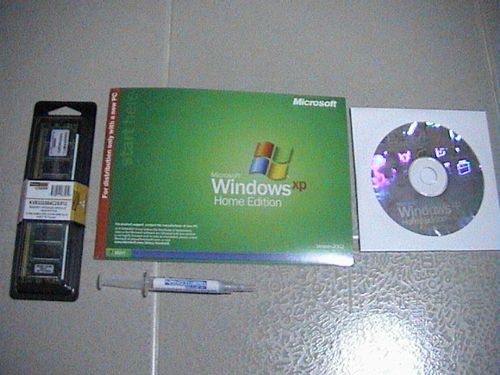
In the following section, I will first describe on installing windows XP (aka experience) onto this newly setup system. The version of Windows XP illustrated here is the Windows Xp Home OEM version. Then later, I will go onto installation for other operating systems.

Just like Vista and Windows 7, Windows XP may be seen to be a savior and an answer in idiot-proof operating system installation. There is nothing much I can tell you what to do in installing Windows xp, as everything is all straightforward and automated- After POST, insert the operating system install CD-ROM (make sure you’ve set the primary boot device to CD-ROM in the BIOS) restart your computer. Sometimes, the system might require you to key “any key” on the keyboard to start the boot from CD, you may have to be alert for that message or the POST will by pass the CD-ROM boot and give you an “Operating system not found message”, requiring you to reboot to try again. One OK, thereafter, your system will detect and read the CD and will prompt you further on the installation.

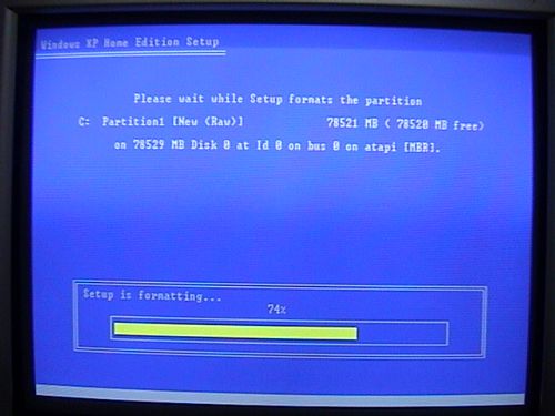
Follow on screen instructions to first format your hard drive (bottom left picture), which may take quite sometime, depending on your hard disk capacity. Then later setup will go on to install the necessary Windows xp system files (bottom right picture).

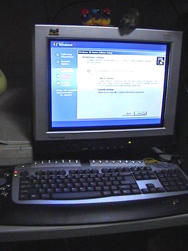
After the setup is complete, your computer will do a final restart (out of the many restarts) and will boot up into the newly installed operation system, do give your computer sometime to configure settings before starting.

Thereafter, you will be rest assured that everything went well when the trademark “rolling hill” background greets you at the end. Then you will have to activate the software by following the help hints on the interface, you can’t really miss it.

Installing other operating systems

Other OS such as Linux and FreeBSD are generally targeted at more advanced users, though installation for these OS now are more slip streamed and easy to install as their proprietary counterparts there is still a degree of technical know how of how the boot and installation process generally goes. This is in particular if you intend to dual boot 2 operating systems on one PC as well, you can either do so with 2 separate hard disks (as each may require a different file format) or create 2 or more partitions on a single harddrive for that.

Older OS requiring floppy disk boot

Certain older operating systems may require you to create a boot disk to run certain command prompt commands an fdisk and an eventual operating system install from a separate CD or floppies like those window 3.11 days. Which is of course, very slow, tedious & cumbersome. The chances of an unsuccessful install is also comparatively very high compared to that of installing XP or it’s successors as stated earlier.

Tip: Even if you have old OS, if possible, try booting from the CD-ROM as far as possible. There is a chance that your OS supports it- you can do this in Windows 98 as well and is much more convenient, not to mention minus the hassle of creating boot disks & such.

Creating the boot disk

If you wish to install Win95, Win98, Win2000 or so but choose (or unable) not to boot from CD, start by creating a bootable floppy disk. This is to load the CD-drivers which are not included in the CD during install so your system can read the CD drive and extract the installation files from there. To create one, simply use another computer, using Win95 OSR2.(B or C) or Win98, select create boot disk on floppy at the ‘My Computer’ section, then the computer will copy the required system files to boot. Alternatively, you can search the net for system boot files to be copied on a floppy, though this is not recommended unless you trust the website providing the boot source.

The following files should be copied onto the floppy itself, with an explanation of each:

MSCDEX.EXE – CD-ROM device driver
FORMAT.COM – Used to format harddrives
FDISK.EXE – Used to create drive partitions
SYS.COM – Used to transfer the System Files to the hard drive and make it bootable.
FORMAT.COM can also be found on the Windows 98 CD in the \WIN98 directory.
CONFIG.SYS – Contains system config commands.
AUTOEXEC.BAT – Contains DOS boot batch programs.

Edit edit CONFIG.SYS and AUTOEXEC.BAT to load the CD-ROM support. More on editing the files can be found here.

Insert the boot floppy & Windows setup CD-ROM into the PC. upon starting up. Ensure that the first boot device is set to “floppy” change the config & reboot if necessary. Upon booting from the floppy, you will see a message stating that a RAM drive was created. If you are installing to a new hard drive, the RAM drive will be none then otherwise, drive C: & you will see a message: ‘Windows has detected that drive C: does not contain a valid FAT or FAT32 partition…blah blah blah’

From here, I will use the following drive letters to represent the following drives

A: Floppy
C: Local Harddrive
D: CD-ROM DrivePartition the Harddrive with FDISK:A:\ FDISK

Press ‘Y’ for large disk support (telling FDISK to create FAT32 partitions).

Choose 1: ‘Create DOS partition or logical DOS drive

Choose 1: ‘Create Primary DOS partition’

Once done, press ESC to exit FDISK, re-boot the PC again with CD-ROM support

Formatting the Hard drive

This time you boot, the RAM drive should move to the next available drive letter (D: if you created one partition). If you are not sure if FDISK was able to partition the whole hard drive, run FDISK again and use option 4 to view partition information. At the command prompt, type:

A:\>D:\FORMAT C: /S

A:\>A:\FORMAT C: /S

The ‘/S’ option will make the hard drive bootable. Next, assign a Volume Label when prompted. However, on some systems with more than 256MB of memory, the /S option of FORMAT.COM may not work. If this is the case, run FORMAT without the /S option.

Alternatively, with CD-ROM support already on, you can key this into the prompt instead:

A:\>D:\WIN98\FORMAT C: /S
(using FORMAT.COM from the CD in drive D:)

Note: However, if you receive a “Bad command or file name” message, you may need to extract the Format.com utility to your startup disk. To do this, type the following command at a command prompt, and then press ENTER:

extract ebd.cab format.com

Later, FORMAT.COM will show the size of the formatted drive, which will always be smaller than the size FDISK reported.

Transfering System Files to the hard drive:

There are two ways you can get about installing the OS. The first by starting the setup straight from the CD itself. The other goes about by copying a copy of the installation cabinet (CABS) files to the hard drive. Though it may take up a considerable amount of hard disk space, you can conveniently access them without the need of a setup disk if you choose to reinstalled the OS again. To do so use the SYS.COM command to transfer the System Files to the hard drive and make it bootable:

OPTION 1: Starting the installation from the CD itself, at the command prompt, type:

A:\CD D:
D:\SETUP

Windows setup will start thereafter.

OPTION 2: Installation from CABS, at the command prompt, type:

A:\>SYS C:

Followed by creating the drive C: CABS directories:

C:\>MD WINDOWS

C:\>MD WINDOWS\OPTIONS

C:\>MD WINDOWS\OPTIONS\CABS

Changing Directory to the Cabinet directory and copy the contents of the Windows 9x or Win2000 CD, to the windows directory on the hard drive:

C:\>CD WINDOWS\OPTIONS\CABS Copying the Install Files to the Hard Drive C:\WINDOWS\OPTIONS\CABS>COPY D:\WIN98

Finally, start the Setup Program
C:\WINDOWS\OPTIONS\CABS>SETUP

The DOS version of SCANDISK will and check drive C:. When it is done, select ‘Exit’ and the windows setup program will load, follow onscreen instructions, reboot & wollia! a working OS.

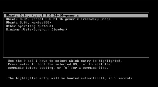
Installing an alternative or secondary OS

Having previously briefly touching on booting with multiple OS, doing so now is very much a piece of cake as the manual work required of the yesterday. Generally for reach first operating system you install, it will write a master boot record (MBR) on the boot sector of the hard disk, this will contain the required information to tell your system on POST that there is an active operating system active on that drive will will call the required files to start the boot process.

An OS will require it’s own partition, the partition can reside on separate hard disks or one made by a partitioning software such as gparted. If you already have a running PC, you can use hard drive partitioning software such as Partition Magic. This is so as each OS may require their own type of file format to run on- Windows prior from Windows ME will require the NTFS format where Linux and Unix variants such as Ubuntu and FreeBSD systems will require the ext2 or ext3 format, their equivalent of the boot loader for Linux will be GRUB.

Running Apple’s Macintosh operating system is very much possible on a PC now, given Apple’s switch to the x86 processor architecture allowing the OS to be booted from a PC-based environment, prior to that, you will need to purchase a pure Mac system due to it proprietary hardware setup. Mac OS X comes standard with a multi-boot features out of the box, with older versions before OS X requiring Apple’s multi-boot utility also known as Boot Camp.

Each OS installs very much like Windows XP which I used as an example earlier, simply just insert the install CD and boot from it at POST, then when choosing a drive to install, chose an empty pre-created partition on your harddisk (or attach an additional hard disk) to format and install all the required files inside. The current residing OS will then add a boot record in the master boot record and will prompt you a time-out selection menu of which OS you wish to boot from each time you power on your PC, it is that simple.

Well, that, that is very much encompass what I have on this tutorial on building and setting up your new PC, let it be a Linux system or a Mac as well. Thanks your for your time in reading this article and I’d be glad if this guide proved useful to you.

Build your own personal computer- Installing CPU and memory

0
Tutorial: DIY steps to build your own personal computer

Installing the CPU and memory

Your motherboard is the base unit which every thing else now is mounted and connected to, with it installed the first item you can start installing will be your computer’s central processing unit or CPU for short.

CPU install

The CPU (central processing unit) aka processor is the most important part of the computer. It happens to be the most sensitive too, so handle it with care.

Tip: It would be advised to earth any charges on your fingers by touching the back earthed metal of a computer casing, this dissipates charges which can short sensitive electronic equipment, permanently damaging them in the process.

It would be easier to install the processor, heat sink and ram out of the system. Place the bare motherboard on a flat clean surface, remove the processor from the packaging and locate the processor socket on the motherboard, it should look like that in Fig 1.1 with the static bag placed below.

Fig 1.1
Fig 1.2

Note that the processor can only be slotted in ONE direction (identified with the pin counts and the cut edge on the bottom left of the chip) Put the processor above the socket and insert it gently. Excessive force will bend or break the processor pins.

Applying Thermal Compound

Thermal compound is of course much better than the inferior thermal pad provided with the heat sink. However, if you do not wish to apply thermal compound your unit, skip this step and head to heat sink installation part.

Fig 1.3
Peel

A small blot of thermal compound is only needed by a processor, (In Fig 1.3) unlike thought by many- more is not always better in this case.

As shown above, I’ve gone on the task of peeling the damn pesky thermal pad of the heat sink. Try not to touch the black surface as it contains thermal conducting paste as well. If it were to stain your heat sink (Fig 1.4) wipe it off with dry fingers. This is one stain where water and tissue is unable to remove.. strangely enough.

Fig 1.4
Clean at last!

Once the heat sink is clean, gently lower the it over the processor (with your previously applied thermal compund) and gently press the two surfaces together till you get some thermal compound onto the heat sink (Fig 1.5) Remove the heat sink (note that you will get equal amounts of thermal compound on both the heat sink and processor) Next, using a CLEAN finger or your finger wrapped with a clean transparent plastic bag, slowly spread the compound all over the surface of the heat sink which you think, will be in contact with the processor. Keep spreading with a massaging & rotating pressing motion until all the compound is thinly compacted and evenly spread on the heat sink (Fig 1.6)

Fig 1.5
Fig 1.6

After that, use a tissue paper and wipe off all excess thermal compound from the heat sink with only 1 or 2 straight clean swipes. Note that upon doing that, you will notice a nice stain on the heat sink produced by the compound (blue in my case) which you can’t wipe off. This is because all the thermal compound you’ve just applied, had all entered the microscopic gaps or crevices of the heat sink metal surface. This is to ensure optimum heat conduction.

Paste spread
Applying on CPU

Back onto the processor, using a clean finger or one wrapped in a plastic bag, spread the thermal compound throughout the top surface evenly and thinly until it it is uniformly thin on the processor surface, as shown below:

Keeping it neat
Close up

Next for tidiness, use a clean razor or plastic card to scrape of overflowing excessive compound from the processor edges, leaving only the paste on top of the processor itself. The thermal compound application is done.

Heatsink Installation

The thermal compound serves as a high grade conductive medium, allowing effectively heat dissipation to the heat sink. When all is done, take the fan and heat sink unit, place it above the motherboard guiding rails and lower is down straight, latching it to the motherboard. Do not perform twisting or any torsional motion downwards as you could smear or potentially mess up the evenness of the the thermal compound. Again, simply just slide the attachment straight down. You might want to give the fitting a some practice tries before actually allowing the heaksink to touch the processor, unless you are sure you can get the heat sink to lock on your first attempt.

Once in place ensure that all holder four latches are in line and secured, thereafter, lock the plastic fan holder containing the heatsink onto the motherboard by locking the plastic levers at the top of the processor assembly, they usually go in opposite directions.

Heatsink in
Fig 1.7
Pluggin in the fan
Slotting in the RAM

Finally, take the lose CPU fan power cable and connect it into the CPU fan power plug on the motherboard (Fig 1.7). In doubt, simply just consult your motherboard manual on the location of the fan power plug, it differs between manufacturers. But be rest assured, its always situated near the CPU socket itself.

There is usually an additional fan output called the system fan (or sysfan0). If you require a fan with variable RPM and can be automatically controlled by your system, you can use this fan at your own discretion, only that you might need to get a molex converter or a 4 to 3 pin converter if you are to use a conventional delta fan. Otherwise, you can ignore this if you are intending to plug your case fans directly into your PSU or a controller of your own.

Installing the RAM

Now onto the RAM, take the ram module and slot it firmly with both hands on each end into slot one (usually nearest to the processor). If the the end latches don’t lock when its slotted, either you have to do so manually or the ram module is not slotted properly. All RAM modules are relatively fool-proof and can only go in one direction, all you need to do is to match the pins length on either side of the DIMM with the motherboard slots. Also, note that the first RAM slot on the motherboard must be always occupied even if the rest aren’t, so always slot them from the first DIMM slot and down.

If you intend to use dual channel RAM, ensure that your RAM modules are of the same make and capacity and slotted in pairs on the same channel for it to work. The slots are usually colour coded and you are usually fine slotting the 2 Modules within the same colour group.

Again consult your motherboard manual on the DIMM slot numbers if you are unsure about that.

Build your own personal computer– Power supply, cabling and power buttons

1
Tutorial: DIY steps to build your own personal computer

Cabling, PSU, case LED lights and power button

With all your major components now assembled, it’s time to link them up with the power supply unit which essentially, feeds power to your your connected components when the system is turned on.

PSU installation

The PSU (power supply unit) provides electrical power to all the components you have on your computer (Eg All drives, motherboard, etc) and send output voltages based on fixed rail voltages – e.g 12volts, 5volts etc. Upon releasing the wired beast from the packaging, locate the ATX 12V power supply plug (20 pin rectangular connector, usually the largest).

This will go into the motherboard ATX power connector plug to power the motherboard and its components, some PSU have an adapter for an additional 4 pins which you can clip along side the 20 pins for motherboards which require 24 pin power connectors, though this is found mostly on newer boards which require a larger power input. Another smaller square 4 pin ATX connector provides power for the CPU (JPW1), the rest of the cables will go into your other components such as drives.

Tip: Do a physical check of the PSU before installing as there may be defects. Always be sure that no internal components of the PSU (eg wires, loose metallic pieces) are sticking out and may come in contact with the external metal casing which could make the exterior casing ‘live’ and could be fatal if touched. Though an installed PSU also grounds the casing our your PC, it pays to always keep that in mind as a safety measure.

Type of power connectors

You will notice that there is quite a few smaller rectangular flat molex 5V power (4pins) connectors, which look as similarly pictured, these are 12 volt supply and will go into your CD-ROM drives and hard drives. Coincidentally, your casing fans will also feature the same molex 4 pin connectors, usually these are labeled “Fan only” and feature 5volt output, these will plug into your casing fans.

Do also note that some fans can take the regular 12 volt output as well, particularly those with additional funky LEDS or temperature readouts and/or with variable RPM with a temperature sensor, these may not even power up on a 5 volt line. If you have many fans, you might want to consider getting a power Y-cable splitter to run more fans in parallel.

Fig 1.1
Fig 1.2

As with most casing, the PSU will normally go at the top back of the casing, secure the unit into the casing using the provided screws and secure it tightly. PSUs can be one of the nosiest units in the whole computer. Insecure PSU rattling in resonance with the spinning fans due to improper fitting of the unit, what’s more the screws connecting the PSU and the case serves as a ground linkage for safety as well so your PC case will never have the risk of being “live”.

IDE Cabling

I believe I touched briefly on hard disk cabling a section before, so this is the part where you physically get to connect them.

SATA or IDE cables are most probably included bundled in your motherboard package, otherwise head down to any computer hardware store and get them. You need one SATA cable for each drive, while an PATA IDE cable can take 2 hard drives in master and slave configuration. The same is for one IDE cable for two CD-ROM/internal Zip drives as well. Lastly, the floppy cable is dedicated for one floppy drive.

Many PC part stores sell cables in different lengths and makes, let be thickness, so if you are using a mid or full tower casing, its good to get longer-than-standard cables for reach. For smaller casings, standard (or shorter) cable lengths are recommended to prevent unnecessary clutter with the casing. Though you can always tie up excess cable with a cable tie for neatness.

ATA cables are used for hardrives for maximum transfer speeds (ATA-100 for 100MBS and ATA-133 for 133MBS), while SATA I & II goes at ATA-150 and beyond, depending on your motherboard generation. SATA is backwards compatible so SATA 3.0 can work with SATA I in generally. The same rule still applies- one SATA cable per motherboard connector per drive device, so there’s no jumpers or configuration to worry about.

For PATA IDE cable, some cables have a third output in the middle of the cable, that output is used only if you are intending to connect a slave drive in that particular IDE port. One end of the ATA cable will connect to the motherboard, on the other extreme end, into your primary master drive (make sure you’ve set the jumper settings corrected to MASTER, head to the previous drives installation section on setting jumpers if you’ve not caught that part).

Floppy cable install

The floppy drive had evolved much over the 5.25″ floppy disks to the 3.25″ variant we see today, these days, floppies are dying out and you usually do not need them considering that PCs these days can boot from thumb drives or external mass storage devices- areas where floppies used to proved invaluable in the past.

Having said that, installing a floppy drive is purely optional now, infact many PC manufacturers do now feature such a drive unless you request for one.

Installing a floppy drive can be a easy one step affair or a nightmare depending on your setup. Unmistakably, the floppy drive has always been the most notorious and troublesome drives to install in computers. Firstly because many manufactures do not follow the same standard settings pin setting and some even manufacturers have them reversed. Installing it is very much of a trail and error game, trying to find the correct slot configuration.

To detect whether you have this problem (widely named as the curse of the floppy drive syndrome), upon turning up your computer later, you will notice that your floppy drive light will always stay on during operation and won’t go off. Try not to insert any floppy disks into the drive when that happens, as it have the capabilities of destroying any floppy disks it consumes.

To fix this “always on problem” when connecting the floppy cable, you must completely stick the the 1st pin to red connector rule. Even if the floppy cable have notches on them, allowing them to be inserted to the drive in one direction, you have to still find a way to get the floppy cable’s 1st red cable (identified as the 1st red wire strip on the cable itself) to be in line with the labeled 1st pin on the floppy drive itself.

My Sony floppy drive have the pins reversed from that of the floppy cable provided by my motherboard manufacturer. Given this problem, you can get another floppy cable with the notch revered, or you can do what I’ve done- I filed the notch on the connector end of of the cable so that it can be inserted into drive in the opposite direction. And wollia it works in the end.

LED lights and power button

Ok, now, onto connecting the LED lights, power and reset buttons of your casing. Firstly, locate the front panel cables in your casing and identify them. Usually it will be a long string of thin coiled wire running internally from the front of your case. These cables are usually attached to a simple push button switch which in turn is simply held in place using glue, so it’s very fragile and you should not tug on this cable. This cable will connect straight to your motherboard power and LED activity pins.

Secondly, from your motherboard manual locate the front panel pin connectors (usually labeled JFP1 & JFP2) JFP2 is a so-called standard specification with only the power button and computer mono speaker functions. While the JFP2 pins, which are of intel specifications, have power and hard drive operation LEDS outputs, reset and power buttons outputs. Plug the respective cables to their motherboard pins.

Power pin JFP1 and JFP2

Following each pin plug, plug each of them into the labeled pins on your motherboard. Some cases have the pins all fitted in a plug which can be fitted only one way and can be inserted with ease, while others might have them separated, so you might want to tape them up with duct tape to make it into a big socket where you can simply just plug into your motherboard.

Generally there are 5 components you need to wire up, you can use the diagram above as an illustration of how the layout could be:

  1. Power button – usually 2-3 pins
  2. Reset button – 2-3 pins
  3. ON LED – 2 pins
  4. Hard drive activity pin – 2 pins
  5. Case speaker (for troubleshooting) – 2 pins

Usually each JFP1 is not isolated to the other, you need to use both of them for a comibination of features can one can work without the other. You can have both the power and HD LEDS, power and reset buttons from the first set and the speaker from the other connector. Do note that the arrangement of the pins differs from motherboard manufacturers, but this shouldn’t be much of a problem.

Well, that’s all about the basic cabling, now to cover on additional miscellaneous cabling you might encounter.

Remaking Sentosa attractions project (Ideas submitted on 1999-2000)

0

Update (July 2009):

Well there had been alot of happenings since I’ve last revisited these ideas for remaking Sentosa. Prior to these submitted ideas, the island is more of less, well just an island with the closure of the fantastic Fantasy island water theme park and the Asian village.

Few developments we see in place currently are the trans-island monorail, the observation tower and the tram rides- ideas submitted from my side at that time. Other than that we do see a Hydro park development at the beach front for surfers as well. Other unrelated ideas will include the lunge ride and the chair lifts.

The great news is that with universal setting up shop on the island now, much of the roller coaster and theme park elements were all considered. Finally Singapore can have a decent roller coaster we can call our own. First off with the dueling Vekoma coasters! Wonder will we be getting Arrows or intamin coasters in, they really rock much better!

Update (July 2002)

I’ve contacted and emailed Sentosa developments on the idea. They thanked and reassured me on the ideas submitted for Sentosa’s redevelopment. But so far there are no says or plans announced. Oh well, its just a matter of time I think.

Well, if you see any new attractions shown here sprouting up in Sentosa, at least you know where it came from!

Concepts (Sent 1999)

I love theme parks & they all have one thing, to satisfy your hunger for thrill and excitement. The thing is that many exciting and trilling rides are not available in Singapore (except for the all too occasional Europe funfairs) Why not have one major theme park right here in Singapore? Designed and built by us here for our people and the world to enjoy! And since Sentosa is currently going on a major overhaul of attractions, why not provide some ideas to aid development? Thats why, my current personal project is that of remaking and redesigning Singapore’s one and only Sentosa. In this sub-section, you will see what ideas, concept art I have for the redevelopment of Sentosa, I personally call ‘Sentosa World’. Ideas here are drawn, built up and accumulated over time. And hopefully one day, Sentosa development corporation would buy my design ideas…

The following are sections (or worlds) in the sentosa world adventure theme park where people can purchase a single day passport to have unlimited rides in the large park for a day or they can choose to have a two day pass, or even a multiday pass with overnight stays in Rasa sentosa. Scroll down to see the various sections (coaster falls, hydro arena, speed freaks and more!)

Personal Ideas currently on work:

  • Flume ride for Hydro Arena
  • Virtual Coaster theaters (mass simulator) for Coaster falls
  • Modern concept ferris wheel for All around rides
  • Viking ship for Hydro Arena
  • High velocity coaster for Coaster falls
  • Slide show cum ride (layout similar to that of the Singapore Story at suntec) for All around rides
  • Crash arena, Bumper cars for All around rides
  • Highlander, High-Intensity coaster (With multiple loops, corkscrews, boomerangs & barrel rolls) for Coaster falls
  • Creeps of the abyss, indoor roller coaster for Coaster falls

Submitted proposed sectors/attractions

Coaster Falls & Hydro Arena (Waterfall theming)

Ride:Escapist
Type: Inverted Coaster

Ride: The Falls 
Type: CorkScrew Roller Coaster

Ride: NA
Type:
Hydro Arena Volcano Beach WaterPark

Speed Freaks (For dizzying speed demons)

Ride: Go Karts
Type: Racing thrill ride

Ride: Terror tower
Type: Free fall ride

Ride: The Chopper

Type:3D rotation thrill ride

Transport and all Rounder Rides (Park transport and for the old, young & those between)

Ride: Sentosa Tram tours
Type: Tram tour ride

Ride: Sentosa Monorail
Type: Monorail train track system

Ride: Observatory Tower
Type:
Double storey roataing observatory